Guide to Heat Exchanger 3D Printing [+Cost Calculator]
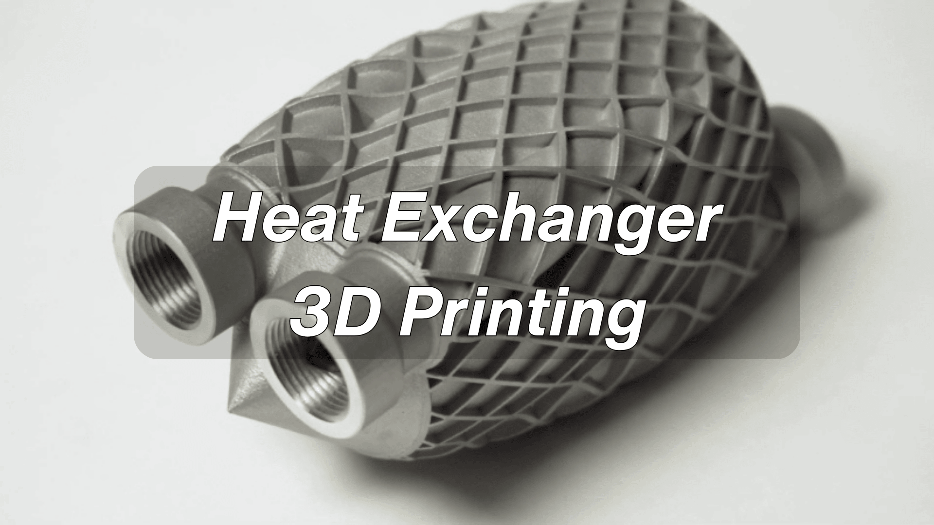
Discover how 3D-printed heat exchangers boost efficiency, cut weight, and enable designs impossible with traditional manufacturing.
Breakthrough Cases Prove the Potential
Across industries from aerospace to electronics, 3D-printed heat exchangers are already redefining thermal management. The real-world success stories below underscore not just feasibility, but superior performance:
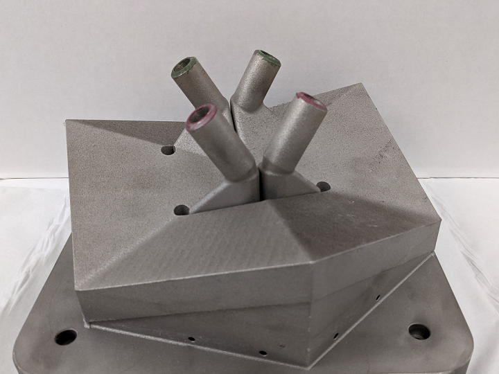
GE UPHEAT Project – Aerospace & Energy:
Source: 3dprint.com
This $3.1M initiative produced a metal AM heat exchanger capable of sustained operation above 900 °C and 3,600 psi. Designed for jet engines and power plants, it enables cleaner, more efficient power generation while reducing carbon emissions.
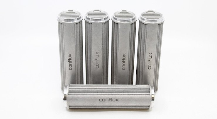
Conflux Technology – Automotive & Aerospace:
Source: TCT Magzine
Leveraging patented lattice geometries via L-PBF, Conflux achieved over 30% higher thermal efficiency while cutting weight and footprint dramatically. The monolithic design eliminates many leak-prone joints, simplifying maintenance and extending service life.
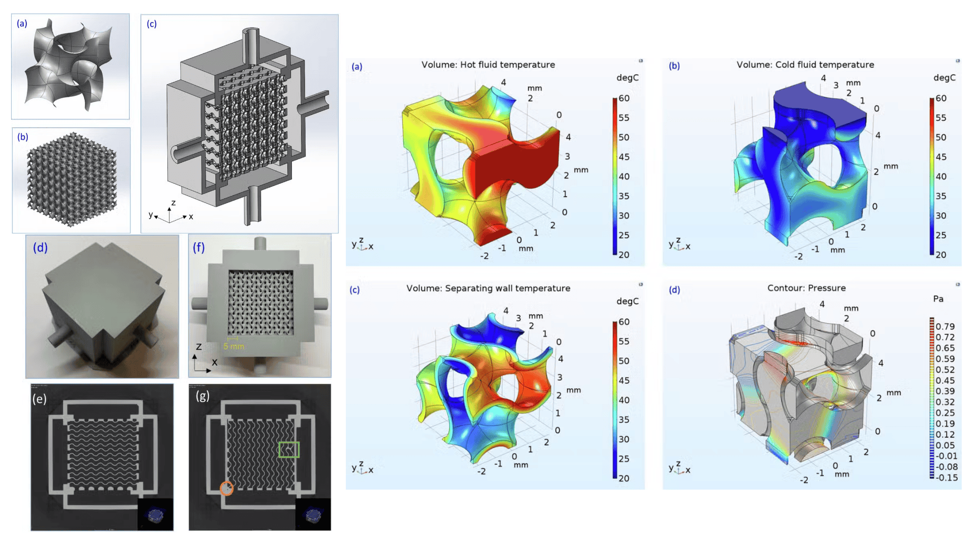
University of Glasgow Gyroid HX – Research & Prototyping:
Source: voxelmatters.com
Using intricate gyroid structures only possible with AM, this compact exchanger delivered ~50% higher effectiveness at roughly one‑tenth the size of a conventional design. Such extreme miniaturization opens new possibilities for high‑performance cooling in constrained spaces.
Together, these cases signal a clear shift: additive manufacturing is breaking through the limits of traditional exchanger design, paving the way for lighter, more compact, and more capable thermal systems.
But what makes additive manufacturing (AM) so disruptive? The answer lies in its departure from traditional production limits.
Conventional Methods: Innovation Bottleneck
Traditionally, heat exchangers are manufactured via:
Brazing and welding join pre-formed plates, tubes, or foils, but the seams limit design freedom and can become leakage points over time.
Machining or chemical etching produce basic channels, yet struggle to create the fine, complex internal paths that high-performance designs require.
These approaches bring recurring pain points:
Geometric constraints
→ Inefficient heat transfer: Flat plates and straight tubes limit surface-area-to-volume ratio and restrict flow complexity, capping performance.
Multi-part assemblies
→ Higher leakage risk: Every joint adds a potential failure point, increasing maintenance costs and downtime.
Heavy weight
→ Higher energy cost: Bulky designs add mass and volume, which is a penalty in mobile or space-limited systems.
Tooling needs
→ Long lead times: Custom tooling slows prototyping and makes design changes costly.
AM removes these constraints entirely by enabling monolithic structures and internal geometries unattainable with subtractive or joining methods.
The Additive Edge: Design, Performance, Impact
Additive manufacturing introduces unique capabilities that translate into measurable thermal, structural, and operational benefits:
Complex Internal Geometries:
AM builds fully enclosed, tortuous channels and gyroid lattices that drastically increase heat transfer surface area.
Topology Optimization:
CFD and FEA tools enable engineers to minimize pressure drop and maximize uniform flow, enhancing effectiveness.
Miniaturization & Compactness:
Systems shrink by up to 80% in volume while maintaining or improving capacity.
Lightweighting:
Lattice-optimized structures cut weight by 50–76%, crucial for aerospace and automotive use.
Production Acceleration:
Lead times drop from months to weeks, allowing faster design iterations and localized manufacturing.
The impact is significant: some AM exchangers offer 30–50% more thermal power for the same size and 6x weight savings.
Navigating AM Challenges
Despite its promise, AM in thermal applications presents several hurdles:
Surface Roughness: May reduce heat transfer efficiency; requires polishing or coating.
Internal Voids: Imperfect fusion leads to leakage; can be mitigated via HIP.
Residual Stress: Causes warping; addressed through thermal annealing.
Quality Inspection: Internal features complicate CT scanning or NDT.
Each issue is actively being resolved through simulation, process tuning, and post-processing best practices.
Choosing the Right Process and Material
Selecting the optimal AM route for a heat exchanger means balancing operating environment, performance targets, and cost constraints.
In most industrial cases, metals remain the dominant choice because they combine high thermal conductivity, mechanical strength, and durability under pressure and temperature extremes—critical factors for reliable thermal management.
Common AM processes
Source: makeagif.com
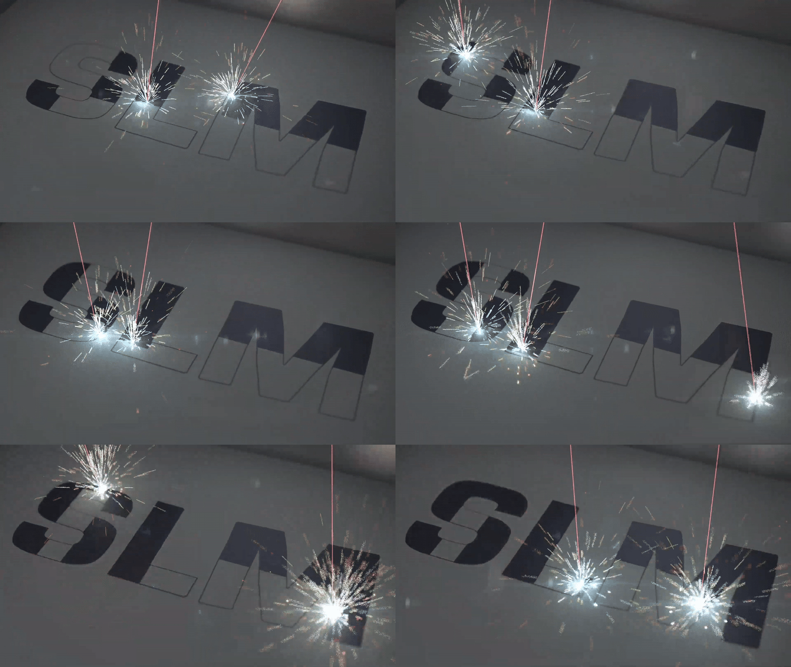
● Metal Laser Powder Bed Fusion (L-PBF) – Also commonly referred to as Selective Laser Melting (SLM), this process uses a high-power laser to selectively melt fine metal powder layer by layer, delivering very fine detail, thin walls, and complex internal channels. Ideal for high-performance designs, though build rates are moderate and post-processing (e.g., HIP) can be extensive.
Source: makeagif.com
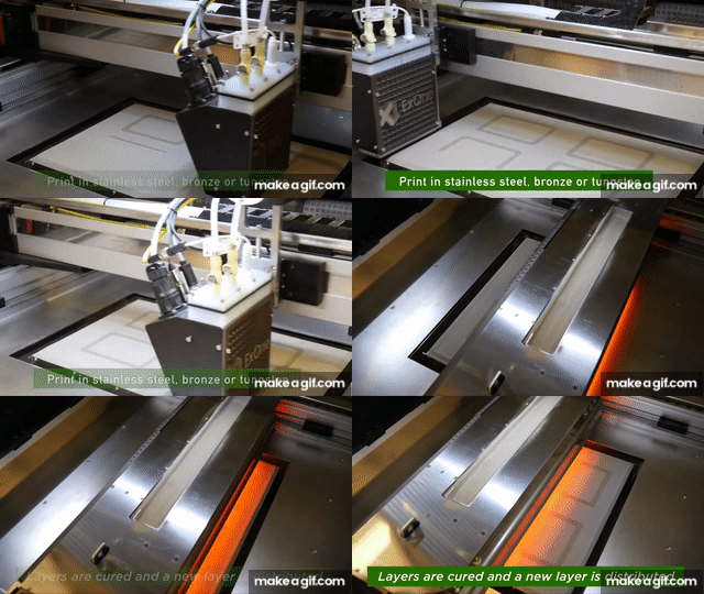
● Binder Jetting (BJ) – Deposits a binding agent onto a metal powder bed, followed by sintering. Enables high throughput and low material cost, with no support structures needed, but final density and surface finish may require improvement.
Representative AM combinations
Process | Material | Max Temp (°C) | Thermal Conductivity (W/mK) | Density (% theoretical) | Corrosion Resistance | Surface Detail (Min. Feature / Ra) | Build Rate | Post-processing Complexity | Typical Lead Time | Unit Cost |
|---|---|---|---|---|---|---|---|---|---|---|
L-PBF | AlSi10Mg | ~400 | ~96.9 | >99% | Moderate | ~0.3 mm / Ra 8–12 µm | Moderate | Medium | 2–4 weeks | $$ |
L-PBF | Inconel 625 | ~1000 | ~9.8 | >99% | Excellent | ~0.3 mm / Ra 8–12 µm | Slow | High (HIP) | 3–5 weeks | $$$ |
L-PBF | Inconel 718 | ~750 | ~11.4 | >99% | Excellent | ~0.3 mm / Ra 8–12 µm | Slow | High (HIP + Heat Treatment) | 3–5 weeks | $$$ |
BJ | 316L SS | ~600 | ~16.2 | ~97–99% | Excellent | ~0.5 mm / Ra 10–15 µm | Fast | Medium | 1–3 weeks | $ |
Selection guidance:
● High-temperature resilience → Use nickel alloys (e.g., Inconel 625 for >900 °C, Inconel 718 for ~750 °C with higher strength) via L-PBF.
● Cost-sensitive projects → Binder Jetting with stainless steel delivers good corrosion resistance at a lower price point.
● Compact and lightweight needs → AlSi10Mg via L-PBF offers high strength-to-weight and excellent machinability for tight spaces.
● Corrosive or water-facing environments → 316L stainless steel ensures long-term durability.
● High surface precision → L-PBF offers the finest features and lowest roughness, while BJ suits less demanding flow-channel tolerances.
● Accelerated delivery requirements → Binder Jetting offers the fastest typical lead times for small-to-medium batch runs.
For tailored advice based on your specifications, talk to Unionfab experts to match the right process–material combination to your project needs.
Understanding 3D Printing Costs
When planning a heat exchanger project, cost estimation is essential for making informed decisions on materials, processes, and suppliers. Knowing where your budget will go helps you optimize both performance and total expenditure.
The following formula breaks down how 3d printing cost is calculated:
Total Cost = Printing Cost (material price × part weight) + Post-Processing Cost + Packaging Fees + Shipping Fees + Customs Duty
Printing Cost
● Material price is calculated per gram (e.g., AlSi10Mg: $0.60/g).
● Weight is calculated from the CAD model’s volume, multiplied by the selected material’s density.
Example: Printing a 300g AlSi10Mg part
Material: $0.60/g
Cost: 300g × $0.60 = $180
Prices are for reference only—please contact our sales team for a formal quotation.
Unionfab’s instant quoting engine gives real-time estimates from your 3D model — Get a Free Quote.
Other Cost Factors
● Post-Processing: HIP, support removal, surface polishing may add 30–50% of base print cost.
● Packaging & Shipping: Costs depend on part volume, weight, and destination.
● Customs: Duties vary by region.
For detailed breakdowns, see our full pricing guide: How Much Does It Cost to 3D Print Something?
Design Principles for Thermal Optimization
To fully harness AM, design must accommodate its physics. Key tips include:
● Wall Thickness: ≥ 0.4 mm for metals
● Channel Diameter: Minimum ⌃ 0.8 mm (metal) to avoid powder clogging.
● Overhang Angles: ≤ 45° to minimize support needs.
● Surface Roughness (Ra): Target Ra < 10 μm post-finishing for optimal flow.
● Powder Removal Holes: At least 1.5x channel size; design for drainage.
● CFD Verification: Use CFD to ensure local Reynolds number > 2,000 to maintain turbulent flow.
For help validating your design, talk to Unionfab experts and Get Free DFM Feedback.
Unionfab's Metal 3D Printing Capabilities
With 20+ years of expertise, 1,000+ industrial 3D printers, and 6 cutting-edge factories, Unionfab, certified with ISO 9001, ISO 13485, and AS 9001D, is committed to delivering high-quality, cost-effective 3D printing services.
The followings are the details of our Metal printing services.
SLM/DMLS | Binder Jetting | |
|---|---|---|
Equipment | BLT; SLM; EOS; EXONE | HP S100 |
Materials | Aluminum (Alsi10Mg) |
|
Max Part Size | 400 x 300 x 400mm | 420 x 420 x 450mm |
Layer Thickness | 0.035 mm | 0.035 mm |
Tolerance | ±0.2 mm | ±0.2 mm |
Min. Wall Thickness | 0.5 mm | 0.5 mm |
Min. Reference Unit Price of Materials | Aluminum (Alsi10Mg): $0.6/g | Aluminum (Alsi10Mg) $0.6/g |
Pass Rate | 99.5% | 99.5% |
Lead Time | As fast as 4-5 days | As fast as 4-5 days |
On-time Delivery Rate | 98% | 98% |
Certification | ISO 9001, ISO 13485, and AS 9001D | ISO 9001, ISO 13485, and AS 9001D |
For professional-grade output, Unionfab is at your service—Get 10 % Discount for your first-time oder.
The Road Ahead: Smart, Scalable, Sustainable
The future of 3D-printed heat exchangers is rapidly evolving:
● Smart Design Integration: Embedding sensors or control features directly into heat exchanger bodies.
● Material Innovation: Polymer composites with near-metal thermal performance.
● Process Automation: Self-correcting AM processes powered by AI-driven feedback loops.
● Cost Scaling: Binder Jetting and new alloys drive down cost per unit.
As demand grows for energy-efficient, compact thermal systems, 3D printing is positioned to lead. Unionfab continues to invest in process reliability, rapid prototyping, and thermal R&D to support global innovators.
FAQs
1. How much does a printed circuit heat exchanger cost?
The cost depends on size, material, and manufacturing method. For 3D printed prototypes, prices may start around a few hundred USD, while industrial-grade printed circuit heat exchangers can cost several thousand USD or more due to high-pressure capability and precision requirements.
2. What is the 2 3 rule for heat exchanger design?
The 2/3 rule is a guideline suggesting that for efficient design, the flow area should be about two-thirds of the total cross-sectional area, balancing pressure drop and heat transfer performance.
3. What is the cheapest type of heat exchanger?
Air-cooled and simple shell-and-tube designs are typically the most affordable. For 3D printing, lattice or polymer-based designs can lower cost, but they are limited to low-temperature applications.
4. What is a gyroid heat exchanger and how does it improve cooling performance?
A gyroid heat exchanger uses a continuous, triply periodic minimal surface structure. This geometry maximizes surface area and promotes turbulent flow, improving heat transfer efficiency while keeping weight low.
5. Where can I find or download a heat exchanger STL file for 3D printing?
You can find open-source heat exchanger STL files on popular 3D model platforms:
GrabCAD – Heat Exchanger Models
Thingiverse – 3D Printed Heat Exchanger Designs
MyMiniFactory – Engineering Components
6. How does a coroplast heat exchanger design compare to other geometries for additive manufacturing?
Coroplast-style designs use parallel channels separated by thin walls, which are easy to manufacture and provide good airflow. However, they usually have less complex mixing than lattice or gyroid geometries, so heat transfer per unit volume may be lower.
7. What are the benefits of using a lattice heat exchanger over traditional fin or plate designs?
Lattice heat exchangers can achieve higher surface-area-to-volume ratios, more uniform temperature distribution, and lighter weight. They also allow integrated manifolds and complex flow paths that are difficult to make with traditional manufacturing.

