Guide to Exhaust Manifold 3D Printing [+Cost Calculator]
![Guide to Exhaust Manifold 3D Printing [+Cost Calculator]](https://ufc-dtc-cms.oss-accelerate.aliyuncs.com/blog/20250713/230747_i4iw08dmh.png)
Learn how 3D printed exhaust manifolds enable faster design, reduced weight, and better flow. Explore SLM tech, top materials, and cost-effective solutions.
Introduction
3D printing, also known as additive manufacturing, is redefining how engineers design and manufacture engine components. Among these components, the exhaust manifold presents a perfect example of where 3D printing can deliver unique value — from design flexibility and faster development cycles to the use of high-performance materials.
In this article, we explain what exhaust manifolds are, how they compare to traditional manufacturing methods, what materials and processes are best suited, and how to optimize design and cost to help you better understand exhaust manifolding 3d printing.
What Is An Exhaust Manifold?

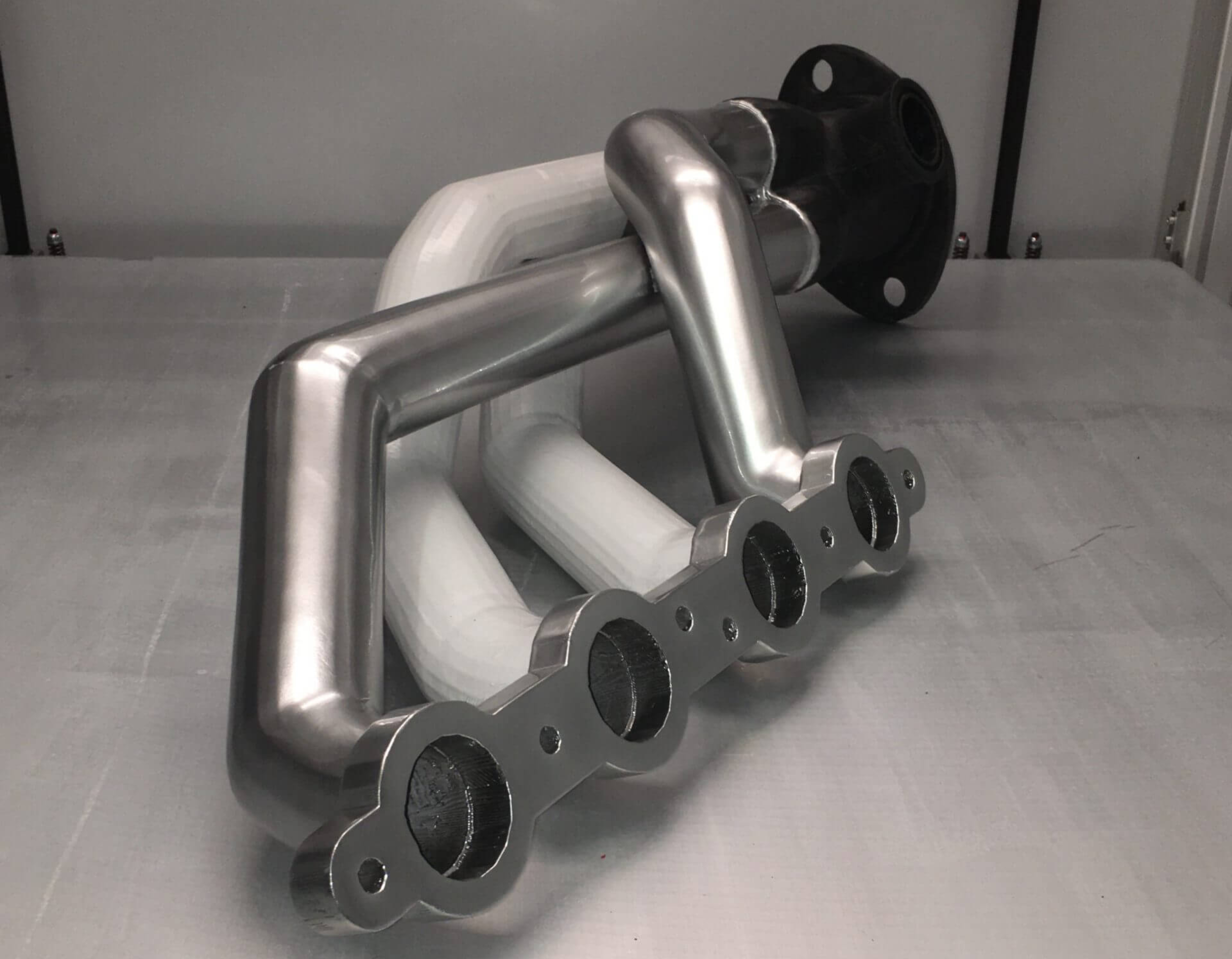
Source: PAMI3D.com
An exhaust manifold is a metal component that connects an engine’s cylinder head(s) to the exhaust system. It collects hot gases from the combustion chambers and directs them through one or more outlet ports.
What It Does:
It connects directly to the cylinder head of the engine.
When the engine burns fuel, each cylinder produces hot exhaust gases.
The exhaust manifold gathers these gases from multiple cylinders (usually 3 or 4 per manifold) and funnels them into a single exhaust outlet.
From there, the gases move through the rest of the exhaust system, including the catalytic converter, muffler, and tailpipe.
Materials:
Usually made from:
Cast iron (durable and handles high heat well)
Stainless steel (lighter, corrosion-resistant, often used in performance applications)
Why It Matters:
A well-designed exhaust manifold reduces back pressure, which helps improve engine performance and fuel efficiency.
It also helps reduce engine noise and ensures gases are expelled efficiently.
In modern applications, especially high-performance and turbocharged engines, the design and material of the exhaust manifold can significantly impact power delivery, thermal management, and durability.
Limitations of Traditional Manufacturing Methods
Traditional Methods Used
Method | Description |
|---|---|
Casting | Commonly sand or investment casting; uses molds |
Welding & Fabrication | Pipes manually bent and welded into shape |
CNC Machining | Applied to surfaces and flanges after forming |
Key Limitations
1. Design Complexity Limitations
a. The ideal shape for exhaust manifolds typically involves smooth curves and equal-length runners to balance gas flow and optimize response.
b. Traditional casting and welding techniques struggle with complex internal geometry, such as gradual transitions or synchronized tube lengths.
c. Designs that require flow uniformity and optimized distribution are difficult to manufacture.
2. Excessive Weight
a. To ensure strength, cast components are often designed thick, resulting in excess weight and reduced fuel efficiency.
b. Welded assemblies require overlaps and reinforcements, further adding structural mass.
3. Thermal Fatigue and Heat Resistance Issues
a. Operating temperatures above 800°C can cause cast iron to crack and weld joints to fatigue.
b. Localized thermal stress is hard to control, reducing lifespan and reliability.
4. Tooling Dependency and Long Lead Times
a. Casting requires molds, which take time and cost to develop.
b. If the design is updated (e.g., optimized gas flow paths), new molds must be produced, making it unsuitable for rapid iteration or small batch production.
5. Precision and Consistency Constraints
a. Post-casting machining is often needed to meet tolerance requirements.
b. Welded structures rely heavily on worker skill, introducing variability.
c. Surface finish and channel consistency are difficult to ensure, which impacts performance.
6. Inefficient Flow Optimization
a. Internal channels cannot be designed with smooth tapers, equal pressure balancing, or optimized flow angles.
b. Poor internal flow contributes to turbulence, back pressure, and reduced engine responsiveness.
These challenges make it hard for traditional methods to meet the lightweighting, thermal durability, and fast prototyping demands of modern engine development.
Why Use 3D Printing for Exhaust Manifolds?
Traditional Limitation | 3D Printing Advantage |
|---|---|
Geometric Constraints | Topology-optimized, internal channels possible |
Excess Weight | Hollow structures and lightweight infills achievable |
Thermal Stress | Advanced alloys (e.g. Inconel) improve fatigue resistance |
Long Tooling Time | No tooling required — faster iteration |
Low Consistency | Layer-by-layer precision ensures tight tolerances |
Poor Flow Design | Smooth, tapered, optimized internal flow paths |
Common Applications of 3D Printed Exhaust Manifolds
3D printed exhaust manifolds are particularly useful in performance-focused, low-volume, or high-complexity applications:
Use Case | Application Example |
|---|---|
Motorsport | Racing engines requiring custom geometry |
Prototyping | One-off parts for concept or experimental vehicles |
R&D | Test benches for engine development |
Aftermarket | Tuning shops producing bespoke manifolds |
Legacy Parts | Replacing discontinued or rare OEM parts |
Recommended Materials and Processes
Selective Laser Melting (SLM) is the most commonly used 3D printing technology for producing metal exhaust manifolds. It enables precise construction of complex geometries from high-performance alloys. The process involves:
● Powder Spreading:
A thin layer of metal powder is evenly spread across the build platform.
● Laser Scanning:
A high-power laser selectively melts the metal powder according to the part's cross-sectional geometry.
● Layer-by-Layer Fusion:
The platform lowers and the process repeats, building the part layer by layer.
● Support Removal and Post-Processing:
Once printing is complete, the supports are removed and the part undergoes post-processing.
Following the SLM process, selecting the right material is critical. Exhaust manifolds demand materials that can resist high heat, corrosion, and mechanical loads. The followings are the detailed comparisons we have made of a range of high-performance 3d printing metals offered by Unionfab.
Temperature Resistance Comparison
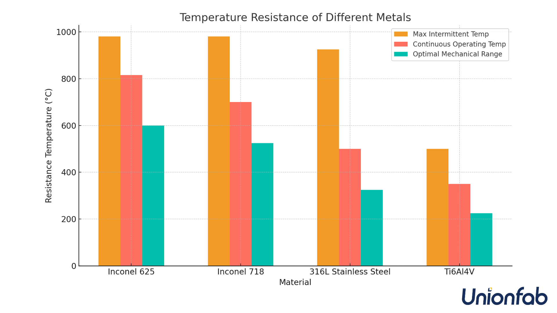
Here is a detailed comparison of Inconel 625, Inconel 718, 316L Stainless Steel, and Ti6Al4V (Titanium Alloy) across three typical temperature dimensions: Max Intermittent Temp, Continuous Operating Temp and Optimal Mechanical Temp Range.

Material | Max Intermittent Temp | Continuous Operating Temp | Optimal Mechanical Range |
|---|---|---|---|
Inconel 625 | ≈ 980°C | ≈ 815°C | 500–700°C |
Inconel 718 | ≈ 980°C | ≈ 650–700°C | 400–650°C |
316L Stainless Steel | ≈ 870–925°C | ≈ 450–500°C | 200–450°C |
Ti6Al4V | ≈ 500°C | ≈ 300–350°C | 150–300°C |
Inconel 625:
Maintains strength and oxidation resistance above 800°C
Withstands short-term temperatures up to 980–1000°C with minimal performance loss
Used in turbo casings, chemical heat exchangers, and aerospace exhaust systems
Inconel 718:
Excellent strength below 650°C. Ideal for high-stress aerospace and turbine applications under moderate heat loads.
Performance drops rapidly above 700°C due to phase degradation.
Widely used in aircraft engines, aerospace structures.
316L Stainless Steel:
Long-term exposure above 500°C can cause intergranular corrosion and strength loss.
Suitable for food-grade equipment, pharmaceutical systems, and chemical piping.
Ti6Al4V (Titanium Alloy):
Thermal stability is weaker than nickel alloys or stainless steel.
Ideal for medium-temp, lightweight aerospace parts and medical implants.
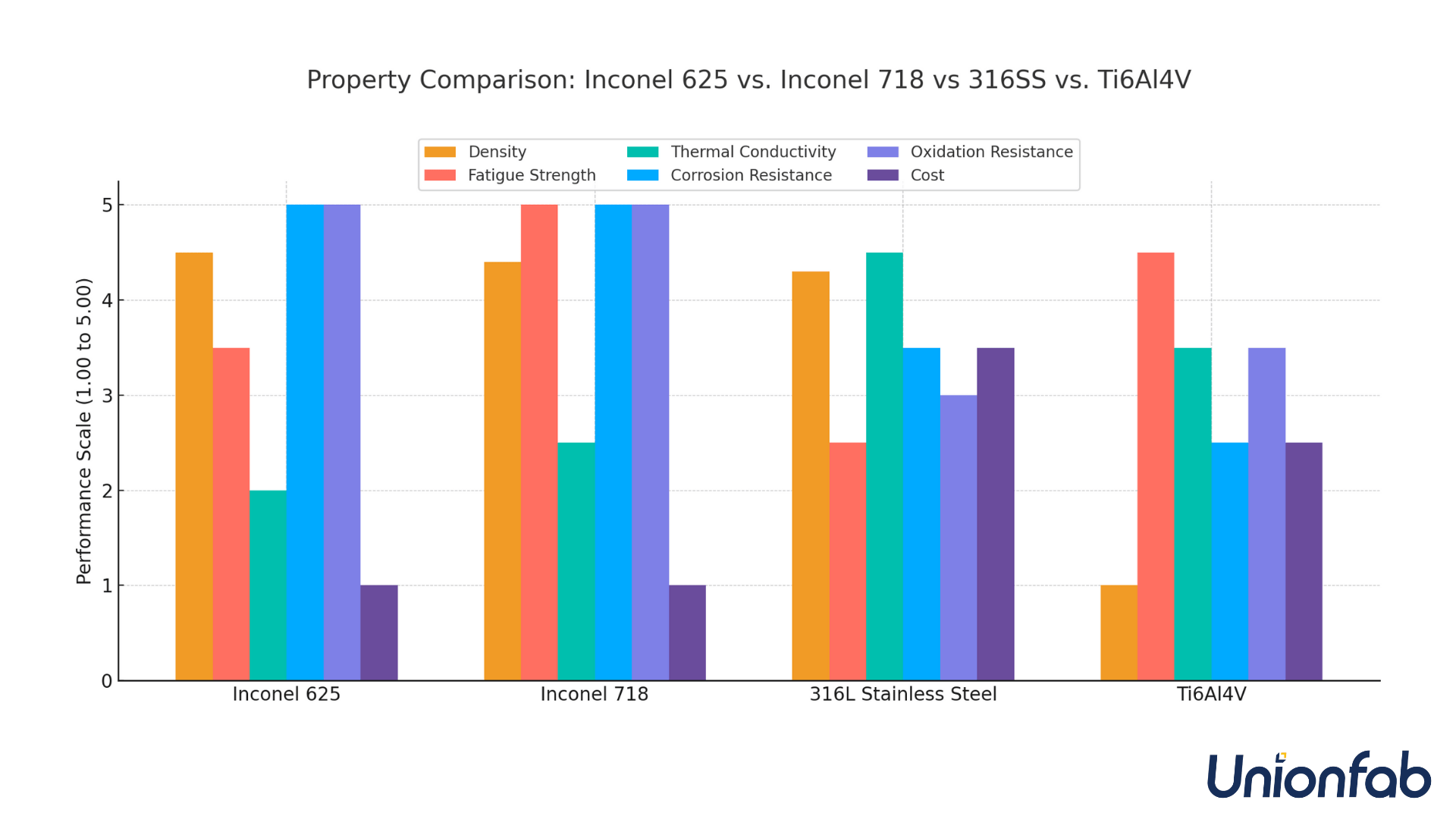
Cost and Other Properties’ Comparison

Property | Inconel 718 | 316L Stainless Steel | Ti6Al4V | |
|---|---|---|---|---|
Density (g/cm³) | 8.44 | 8.19 | 8.00 | 4.43 |
Fatigue Strength (MPa) | 300–620 | 620–700 | 240–380 | 510–620 |
Corrosion Resistance (rating) | Excellent | Excellent | Good | Moderate |
Thermal Conductivity (W/m·K) | 9.8 | 11.4 | 16.3 | 6.7 |
Oxidation Resistance (rating) | Excellent | Excellent | Moderate | Good |
Cost (relative) | High | High | Medium | Medium–High |
Among these, Inconel 625 stands out as the top choice for exhaust manifold applications due to its exceptional heat resistance and stability under thermal cycling. This makes it highly suitable for turbocharged or high-performance engine environments.
To learn more, read our full guide: Inconel 3D Printing: A Complete Guide.
Unionfab experts will recommend the most appropriate material based on your functional, thermal, and mechanical requirements. Talk to Unionfab Experts — for technical advice tailored to your project.
Post-Processing Options
To ensure part integrity and optimal surface quality, 3D printed exhaust manifolds undergo various post-processing steps:
Step | Purpose |
|---|---|
Heat Treatment | Relieve stress and improve material strength |
Surface Finishing | Improve gas flow and appearance |
Machining | Achieve tight tolerances on mounting surfaces |
Testing | Leak and dimension verification |
Unionfab provides all these post-processing services in-house for reliable, end-to-end production.
How Much Does It Cost to 3D Print an Exhaust Manifold?
The total cost of SLM 3D printing generally consists of four key elements: material cost, post-processing cost, logistics, and taxes. Here's a breakdown of how each component is typically calculated:
Material Cost
Material cost is determined using the following formula, which often includes both raw material and printing service fees:
Material Cost = Model Volume × Material Density × Material Price per Gram
In most cases, the more parts you produce, the lower the overall unit cost becomes.
Post-Processing Cost
Post-processing expenses depend on factors such as part size, complexity, material, and the required finishing operations. Common pricing models include:
● Hourly rate: Used for detailed tasks like machining or surface polishing.
● Per-part rate: Suitable for basic finishing work.
● Weight/volume-based rate: Often applied to labor- or energy-intensive processes like heat treatment.
Logistics and Taxes
Shipping costs are typically based on part weight and shipping distance, and may vary by region or service provider. Tax rates depend on local regulations and are usually calculated as a percentage of the total service cost.
For a more comprehensive explanation of these factors, read our previous article:
👉How Much Does It Cost to 3D Print Something ?
For a more personalized estimate, you can use our online 3d printing cost calculator to determine the exact cost based on your part specifications and material choice.
Design Guidelines for 3D Printed Exhaust Manifolds
Besides choosing the right material, the performance of a 3D printed exhaust manifold relies heavily on effective design.
The following modeling guidelines address the unique demands of exhaust applications.
1. Internal Flow Path Optimization
● Create smooth, continuous internal channels and avoid sharp corners or abrupt transitions that minimize back pressure and improve gas evacuation.
● When designing multi-cylinder manifolds, maintain symmetrical and equal-length runners to promote even exhaust distribution and maximize engine efficiency.
2. Thermal Expansion & Stress Relief
● Exhaust manifolds undergo extreme thermal cycling, so :
Include flexible curves and stress-relief zones in your geometry to absorb expansion forces.
Avoid rigid or abrupt changes in shape that may concentrate thermal stress—especially around flanges, joints, and high-load areas.
● Use FEA simulation to predict deformation and apply pre-compensation strategies in the design phase.
3. Topology Optimization for Strength and Weight
● Apply topology optimization tools to reduce weight while maintaining structural strength under thermal and mechanical loads.
● Focus on load paths, flange regions, and cantilevered supports, ensuring smooth transitions and continuous geometry.
● Incorporate internal ribs or lattice reinforcements in low-stress zones for improved vibration resistance and strength-to-weight ratio.
4. Wall Thickness Control
● Maintain uniform wall thickness between 2.5–5 mm to ensure consistent heat distribution and structural integrity.
● Avoid drastic changes in thickness that can lead to hotspots or cracking under thermal stress.
● Allow for machining tolerance in mounting surfaces or sealing flanges as needed.
5. Printability and Support Strategy
● Design with ≥45° self-supporting angles where possible to minimize the need for internal supports.
● Ensure easy access for post-processing and powder removal in enclosed channels.
● For complex internal geometries, consider adding vent holes or powder evacuation ports to enable cleaning and reduce trapped material.
6. Mounting and Integration Design
● Integrate mounting holes, sealing surfaces, dowel features, and flanges directly into the CAD model.
● For turbocharger or downstream component connections, design thermal expansion joints and seal grooves to accommodate movement and heat cycling.
● Consolidate multiple components into a single, monolithic part—reducing assembly time and tolerance stacking.
Summary: Modeling Goals and Strategies
Design Goal | Modeling Strategy |
|---|---|
Reduce exhaust back pressure | Smooth curves, equal-length runners, gradual merges |
Resist thermal fatigue | Stress-relief transitions, uniform wall thickness, FEA-driven compensation |
Maximize strength-to-weight | Topology optimization, structural ribs, smooth load paths |
Ensure printability | Self-supporting angles, access for support removal, internal vents |
Simplify installation | Integrated flanges, threaded holes, one-piece consolidation |
Partner with Unionfab for High-Performance Metal 3D Printing Solutions
The followings are the details of the metal 3d printing service we provide:
Feature | Description |
|---|---|
Technologies andMaterials Available | SLM/DMLS:Aluminum(AlSi10Mg; 6061)316L Stainless Steel 17-4PH Stainless SteelMaraging SteelTitanium(TC4) Inconel 625CuCrZrBinder Jetting: 316L (Single Alloy); 17-4PH |
*Maximum Part Size | 420 x 420 x 450 (mm) |
General Tolerances | L<100mm: ±0.2mm, L>100mm: ±0.2%*L |
General Surface Finish | Ra 3.2 |
Standard Lead Time | 3~7 business days |
*Note: 420 x 420 x 450 (mm) is just the maximum size for a single print. For larger parts, we can split the model into sections, print them individually, and weld them together seamlessly.
If you're new to Unionfab's services, sign up to get a 10% discount on your first order. Our price is up to 50% lower than competitors.
Cases Display
Here we have displayed the metal prints that we have finished across different industries.
Industry | Case |
|---|---|
Automotive | Wheel Hub Made of Stainless Steel 316 L SLM Printed Automotive Parts |
Aerospace | SLM Printed Exhaust Nozzle SLM Printed Aluminum Alloy Aircraft Components |
Industrial | 3D Printed Conformal Cooling Channels SLM 3D Printed Heat Sink |
Medical | SLM Printed Prosthesis and Implants SLM Printed Spine Corrector |
Design | SLM Printed Metal Pen SLM Printed Colorful Terra Cotta Warriors |
FAQs
Q: What is a 3D printed exhaust manifold used for?
A: A 3D printed exhaust manifold is used to collect and channel exhaust gases from the engine's cylinder head to the exhaust system. It is ideal for performance engines, prototypes, and custom applications where lightweight and optimized flow design are required.
Q: What materials are best for 3D printed exhaust manifolds?
A: High-temperature alloys such as Inconel 625 and Inconel 718 are commonly used due to their excellent thermal resistance and mechanical strength. Stainless steel 316L is also popular for moderate-temperature applications.
Q: How long does it take to 3D print an exhaust manifold?
A: Depending on size and complexity, printing can take between 12 to 48 hours, followed by post-processing steps such as heat treatment and machining. The full turnaround time is typically under one week.
Q: Is 3D printing cost-effective for low-volume production of exhaust manifolds?
A: Yes. Since it eliminates the need for tooling and allows for design flexibility, 3D printing is especially cost-effective for low-volume, custom, or prototyping scenarios.

